
单片机_stc89c52_驱动外设
驱动led
原理
由原理图可知,LED一段都接了电源,另一端接了单片机的P20~P27引脚 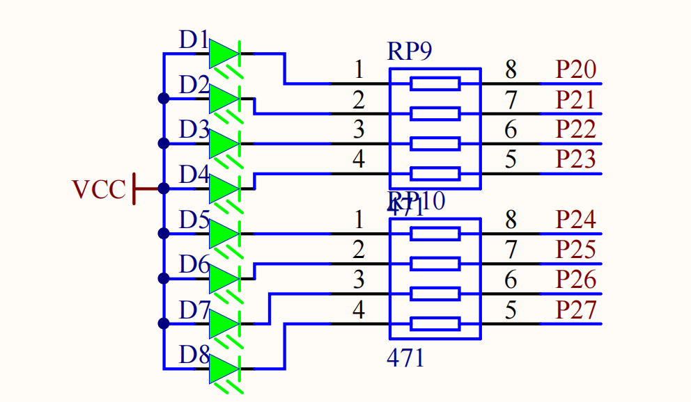 因此,
因此,P2 引脚为低电平时就可以点亮LED,可以整体赋值
P2 = 0xFE;也可以单个赋值(头文件为<REGX52.H>)
P2_7 = 0;示例
点亮LED
独立按键
原理
原理图
由原理图可知,按键一段都接了低电平,另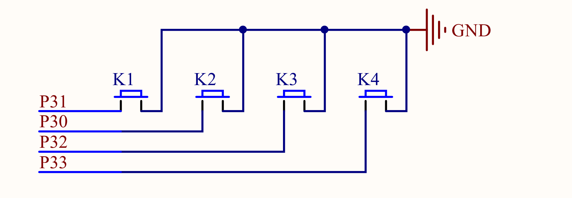 e%2020260129182308.png) 当单片机给按键低电平的时候,就导通了
按键消抖
if (P3_1 == 0) {
	DelayMs(20); // 按下消抖

	while (P3_1 == 0); // 松手消抖
	DelayMs(20);

	LedToggle();
}示例
按键点亮led
[002_key_pressed_debounce](https://github.com/Zhuang-xd/blog-giscus-page/tree/master/stu[](../public/images/GIF_20260129_182151.gif)
二进制点灯
[003_key_pressed_bin_add](https://github.com/Zhuang-xd/blog-giscus-page/tree/mast
数码管
原理
原理图
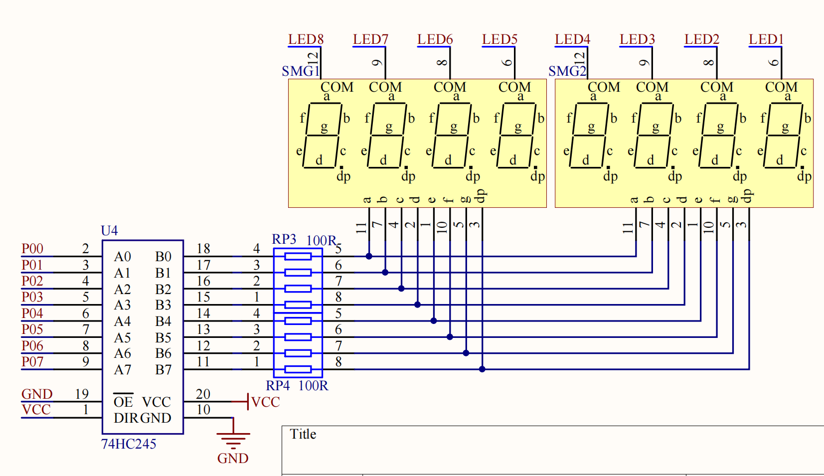
8个数码管通过74hc595管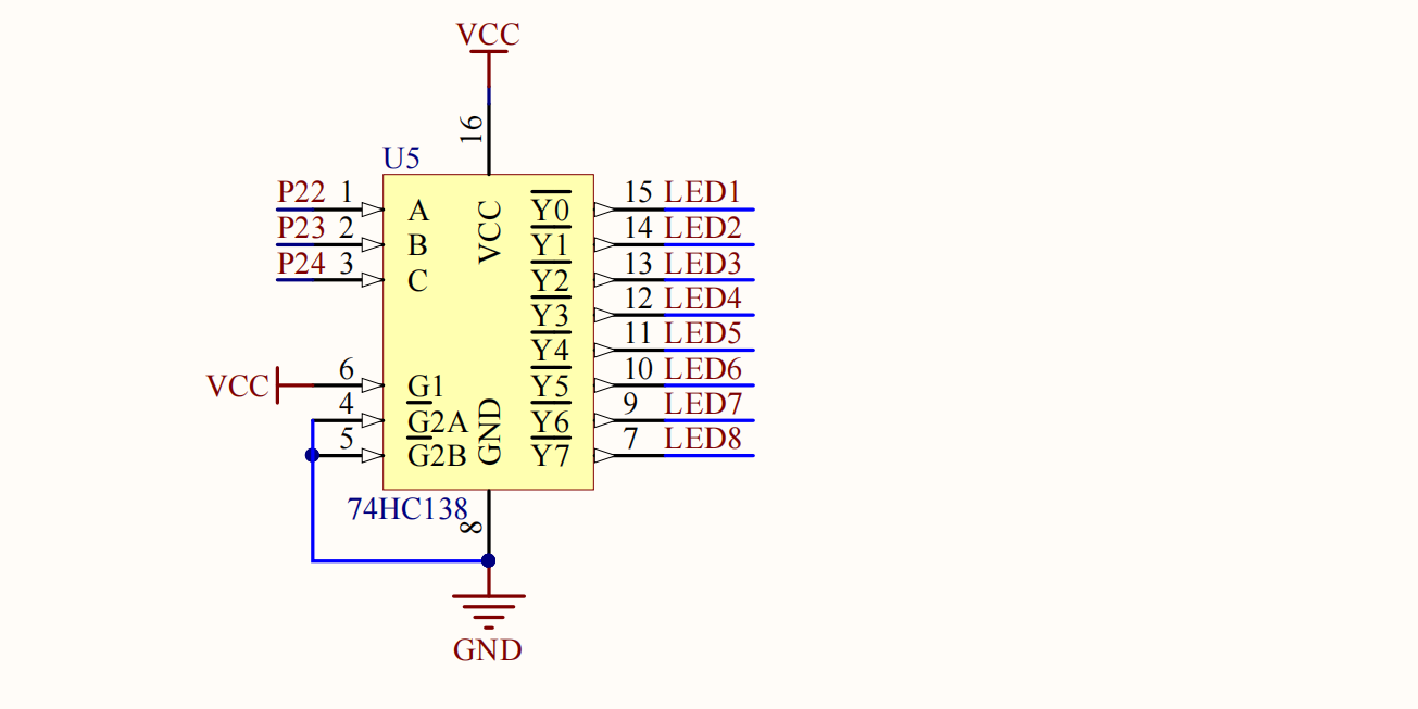
 ng)
ng)
显示单个数码管
原理图上的数码管的COM端没有接VCC,因此时共阴极的数码管,码表为
unsigned char seg[17] = {
			// 共阴极,高电平有效
			//  7 6 5 4   3 2 1 0
			// dp g f e   d c b a
	0x3F,	//  0 0 1 1   1 1 1 1  = 0
	0x06,	//  0 0 0 0   0 1 1 0  = 1
	0x5B, 	//  0 1 0 1   1 0 1 1  = 2
	0x4F, 	// "3" a b c d g
	0x66, 	// "4" b c f g
	0x6D, 	// "5" a c d f g
	0x7D, 	// "6" a c d e f g
	0x07, 	// "7" a b c
	0x7F, 	// "8" 全亮
	0x6F, 	// "9" a b c d f g
	0x77, 	// "A"
	0x7C, 	// "B"
	0x39, 	// "C"
	0x5E, 	// "D"
	0x79, 	// "E"
	0x71, 	// "F"
};显示多个数码管
while (1)
{
	for (i = 0; i < 8; i++)
	{
		seg(i,i); // 第i个数码管, 显示i
	}
}


void seg(int sel_seg, int sel_chip)
{
	switch (sel_seg)
	{
	case 0: P2_4 = 0; P2_3 = 0; P2_2 = 0;break;
	case 1: P2_4 = 0; P2_3 = 0; P2_2 = 1;break;
	case 2: P2_4 = 0; P2_3 = 1; P2_2 = 0;break;
	case 3: P2_4 = 0; P2_3 = 1; P2_2 = 1;break;
	case 4: P2_4 = 1; P2_3 = 0; P2_2 = 0;break;
	case 5: P2_4 = 1; P2_3 = 0; P2_2 = 1;break;
	case 6: P2_4 = 1; P2_3 = 1; P2_2 = 0;break;
	case 7: P2_4 = 1; P2_3 = 1; P2_2 = 1;break;
	}

	P0 = seg[sel_chip];
	DelayMs(1);
	P0 = 0;
}示例
点亮单 om/Zhuang-xd/blog-giscus-page/tree/master/study_chip_51/src/004_segment_single)
点亮多 /Zhuang-xd/blog-giscus-page/tree/master/study_chip_51/src/005_segment_multiple)
 和数码管类似,通过单片机的
 P10 ~ P17 引脚,4个表示列,4个表示行,可以检测16个按键。 先选中一行,再扫描一列就可以确定哪个按键被按下了  key](https://github.com/Zhuang-xd/blog-giscus-page/tree/master/study_chip_51/src/009_matrix_key)
按键密码锁
[010_matrix_key_l
t
原
d%20image%2020260114224143.png)
// 点阵屏扫描
void Int_matrix_led_scan_col(u8 col, u8 byte)
{
    Int_74hc595_send_byte(byte);
    P0=~(0x80>>col); // 1000 0000位移1位后取反 1011 1111,可以实现相同的逻辑
    // P0 = _cror_(0x7f,col); // 0111 1111
    Com_Util_DelayMs(1);	//延时
    P0=0xff;	//位清0
}

void Int_74hc595_send_byte(u8 byte)
{
    u8 i;
    for (i = 0; i < 8; i++)
    {
        SER = byte&(0x80 >> i); // 由高到底发送
        SRK = 1; // 上升沿移位
        SRK = 0; // 上升沿移位
    }
    RCK = 1; // 上升沿8位锁存
    RCK = 0; // 上升沿8位锁存
}按列显示0点亮,一共8列,因此可以通过8个8位表示一帧画面
unsigned char code bmp[]={
0x00,0x7E,0x10,0x10,0x7E,0x00,0x00,0x7E,
0x52,0x52,0x52,0x00,0x00,0x7E,0x02,0x02,
x42,0x42,0x3C,0x00,0x00,0x7A,
};第二帧画面为
Int_matrix_led_scan_col(i,bmp[i+offset]);
offset++;注意
跳线帽改成如图,点阵屏才能正常显示 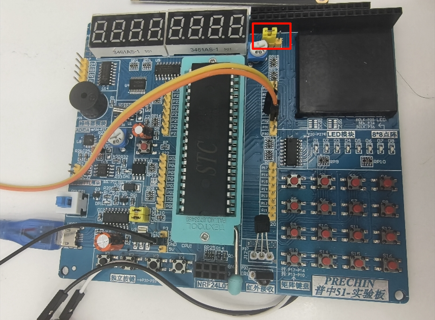
示例
摄像头拍不出,动态显示心形
摄像头拍不出,滚动显示HELLO
DS1302时钟
原理
示例
时钟
时钟设置
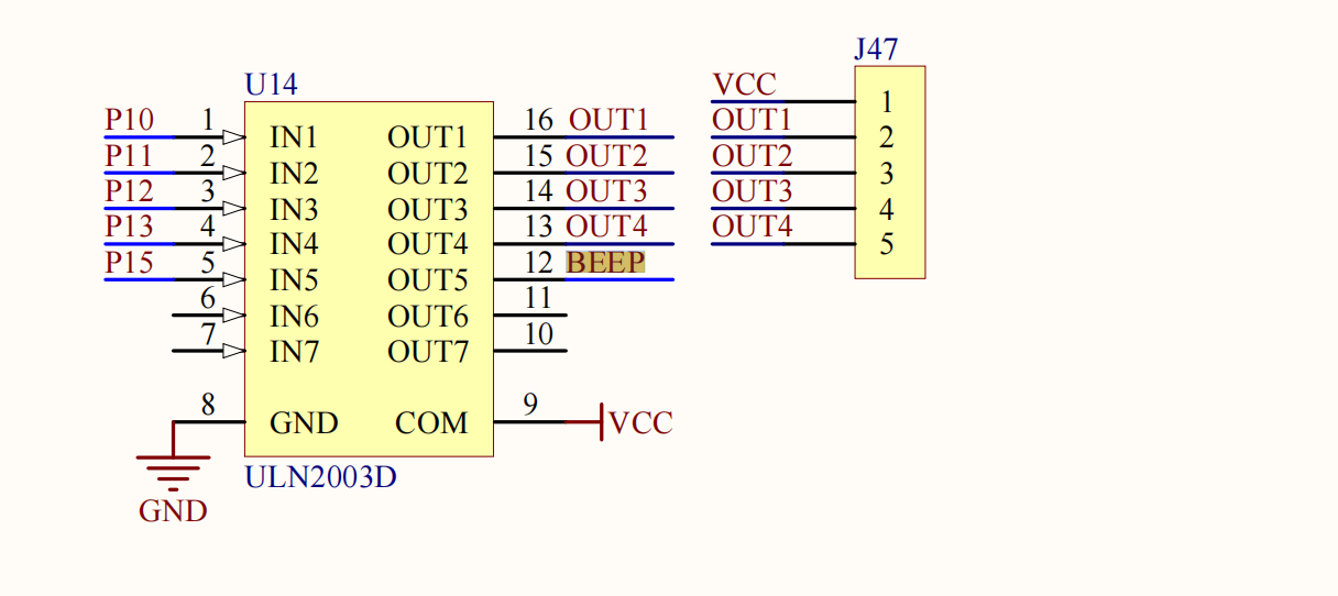
蜂鸣器
原理
有源蜂鸣器通电就可以响,但是开发板上是无源蜂鸣器,因此需要提供一个PWM方波来驱动蜂鸣器 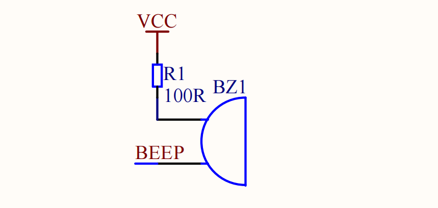
示例
019_beep_key [020_beep_music](https://github.com/Zhuang-xd/blog-giscus-page/tree/master/study_chip2内部有一个字库,可以自动将ASCII码转换成对应的字符。
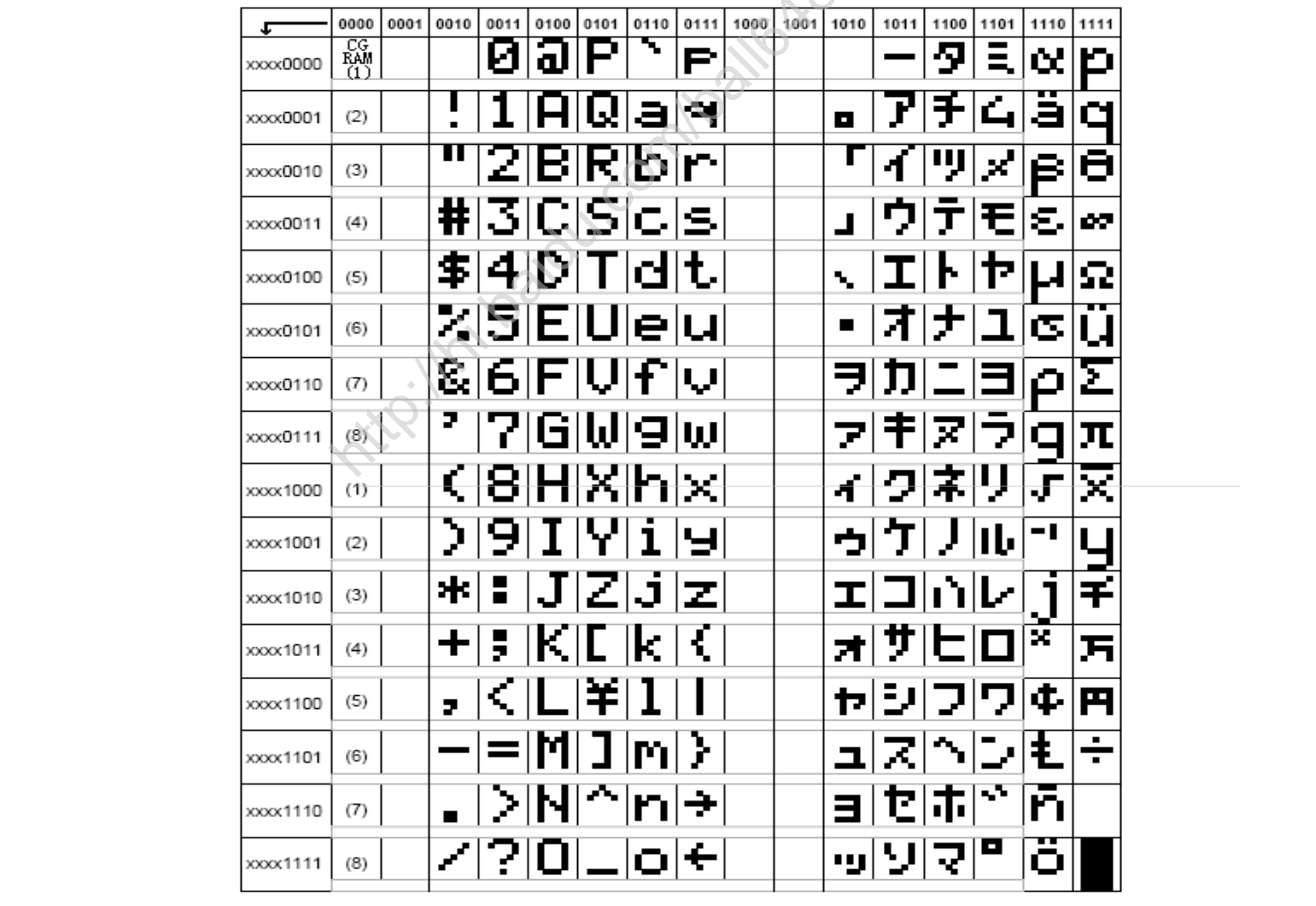
LCD1602有2行,每行16个字符:
- 第0行的地址范围:
0x80~0x8F - 第1行的地址范围:
0xC0~0xCF
主要由三个控制引脚:RS、RW、EN 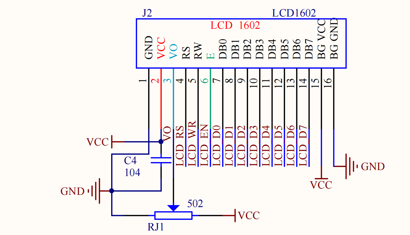
示例
sbit LCD1602_EN = P2^7; // 1读  下降沿执行指令
sbit LCD1602_RS = P2^6; // 0指令 1数据
sbit LCD1602_RW = P2^5; // 0写   1读

void Int_LCD_Init()
{
    Int_LCD_WriteCmd(0x38); // 设置8位格式
    Int_LCD_WriteCmd(0x0c); // 整体写入
    Int_LCD_WriteCmd(0x06); // 设置输入
    Int_LCD_WriteCmd(0x01); // 清屏
    Com_Util_DelayMs(1);
}

void Int_LCD_WriteCmd(u8 byte)
{
    LCD1602_SDA=byte;
    LCD1602_RS=0;               //指令
    LCD1602_RW=0;               //写入
    LCD1602_EN=1;
    Com_Util_DelayMs(1);
    LCD1602_EN=0;               //下降沿
    Com_Util_DelayMs(1);
}

void Int_LCD_WriteData(u8 byte)
{
    LCD1602_SDA=byte;
    LCD1602_RS=1;               //数据
    LCD1602_RW=0;               //写入
    LCD1602_EN=1;
    Com_Util_DelayMs(1);
    LCD1602_EN=0;               //下降沿
    Com_Util_DelayMs(1);
}

void Int_LCD_ShowChar(u8 line, u8 pos, u8 ch)
{
    u8 addr;
    // 1000 0000
    addr = (line == 0) ? 0x80+pos : 0xc0+pos; // 0xc0 = 0x80 + 0x40
    Int_LCD_WriteCmd(addr);
    Int_LCD_WriteData(ch);
}